* These are Tibbo BASIC/C-programmable devices and their function depends on the loaded app.
We offer many ready-to-use apps, among them a serial-over-IP (SoI) app and Modbus Gateway app.
TPS OverviewMainboards (TPPs)Tibbit BlocksProject Box Enclosures (TPBs)AppBlocks Platform

Tibbit® Blocks

Tibbits (as in "Tibbo Bits") are blocks of prepackaged I/O functionality housed in brightly colored rectangular shells.

Tibbits implement a wide variety of I/O functions. Want an ADC? There is a Tibbit for this. 24V power supply? Got that! RS232/422/485 port? We have this, and many other Tibbits, too.

Tibbits are divided into Modules ("M" devices) and Connectors ("C" devices). There are also Hybrid ("H") Tibbits that are a cross between Modules and Connectors.

Tibbits are an integral part of our Tibbo Project System. They plug into Tibbo Project PCBs (TPPs) and fit our Tibbo Project Box (TPB) enclosures.

M1 "Narrow" Tibbit Modules

M1 Tibbits are single-width modules occupying one Tibbo Module socket on a Tibbo Project PCB (TPP). Their footprint is roughly 7 x 14 "squares" (one "square" is 2.54 x 2.54 mm or 100 x 100 mil).

M1 devices have four I/O lines for interfacing with the outside world. We found four to be the magic number. It's just right for a wide variety of I/O functions.

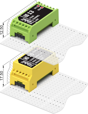
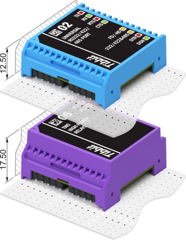
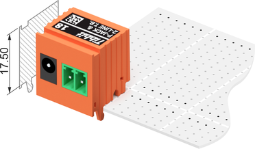
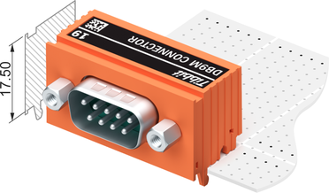
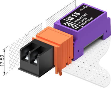
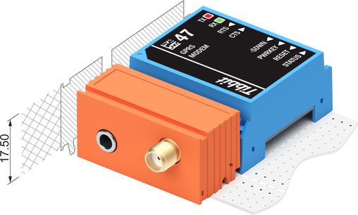
M1s can be short (M1S) or tall (M1T). Most M1 devices fit into "short" 12.5mm shells, selected few are 17.5mm "tall."

Each M1 Module's color tells you if it is an...

Input
Module
Output
Module
Input/
Output
Power
Supply
Direct
I/O Lines
Narrow Tibbit Modules

M1 modules have 2 rows of 6 pins:

Pins 8-11 are control lines A-D. They are for interfacing to the main CPU of Tibbo Project PCBs (TPPs).

Pins 2-5 are I/O lines facing the outside world. On Tibbo Project PCBs they go to Tibbit Connectors (described below).

Pins 6 and 12 are the GROUND and +5V power pins. Most Tibbit Modules consume (take) 5V power. There are also power supply Tibbits that generate 5V power from a variety of sources. Those output 5V through pin 12.

Pins 1 and 7 are for the additional +15V and -15V supply voltages. These are optional and only needed by a few Tibbits. A special power supply Tibbit#12 generates +/–15V from the main 5V power.

M2 "Wide" Tibbit Modules

M2 Tibbits are double-width modules occupying two standard Tibbit Module sockets on a Tibbo Project PCB. They are roughly 14 x 14 "squares."

With double the size comes the doubled internal space and I/O capacity. M2s have eight I/O lines. They are used for "grander things" that just wouldn't fit into the M1 form factor.

Like M1s, M2 devices can be short (M2S) or tall (M2T).

The color coding scheme is the same:

Input
Module
Output
Module
Input/
Output
Power
Supply
Direct
I/O Lines
Wide Tibbit Modules
Wide Tibbit Modules

M2 modules have 4 groups of 6 pins arranged into 2 rows:

Pins 14-17 and 20-23 are control lines A-H.

Pins 2-5 and 8-11 are I/O lines.

Pins 12 and 24 are the GROUND and +5V power pins.

Pins 1 and 13 are for the optional +15V and -15V voltages.

Pins 6, 7, 18 and 19 are unused and should be left unconnected.

Notice that each pin row has a "missing pin" in the middle. This separates a row into two groups of 6 pins.

C1 "Narrow" Tibbit Connectors

C1 devices are single-width Tibbit Connectors. On a Tibbo Project PCB they occupy one standard Tibbo Connector socket and install in front of Tibbit Modules. C1s have the equal width and height with M1T devices.

Some C1s are really just connectors of the power jack, terminal block, etc. variety. Others "sense" the outside world: they measure temperature, humidity, vibration, and so on.

C1 Tibbits are always orange.

Narrow Tibbit Connectors

C1 Tibbits have a single row of 4 pins. All four pins are I/O lines that connect directly to four I/O lines of the neighboring Tibbit Module socket.

There are no dedicated ground and power pins. Many C1s don't need ground and power anyway – they house connectors and nothing else.

If an attached external device needs ground and power, then these must come from the Tibbit Module. Ground and power are also necessary for "sensor" Tibbit Connectors.

C2 "Wide" Tibbit Connectors

With double the width of C1s, C2 Tibbits are wide enough to house DB9 connectors and 9-row terminal block banks.

On a Tibbo Project PCB they occupy two standard Tibbo Connector sockets and install in front of Tibbit Modules. C2s have the equal width and height with M2T devices.

C2 Tibbits are always orange.

Wide Tibbit Connectors

C2 Tibbits have a single row of 11 pins:

Pins 1-4 and 8-11 are I/O lines that connect directly to the I/O lines of two neighboring Tibbit Module sockets.

Pin 5 is the +5V power pin.

Pin 6 is the ground pin.

Pin 7 is the +15V power pin (Tibbit#12 is required to generate this voltage).

Since C2 devices have dedicated ground and power lines they are not dependent on Tibbit Modules for power and ground, as C1s are.

There is no provision for connecting -15V power. If any C2 device needs -15V then this must be supplied by the neighboring Tibbit Module.

H1 "Hybrid" Tibbits

H1 Tibbits are merged M1T and C1 devices. They occupy the combined space of one M1 and one C1 Tibbit.

The H1 form factor is used when it is unsafe or undesirable to interconnect M1 and C1 Tibbits via a Tibbo Project PCB. Examples of such cases are high-voltage and high-frequency (radio) circuits.

Narrow Hybrid Tibbits

H1 devices have no pins on their C1 "section." Pins on the M1 section have the standard positioning, except that some of the pins 1-6 may not be present.

For example, it is not unusual for an H1 device to only have pin 6 (GROUND) in the left row of the M1 section.

H2 "Hybrid" Tibbits

H2 Tibbits are merged M2T and C2 devices. They occupy the combined space of one M2 and one C2 module.

The H2 form factor is used when it is unsafe or undesirable to interconnect M2 and C2 Tibbits via a Tibbo Project PCB. Examples of such cases are high-voltage and high-frequency (radio) circuits.

Wide Hybrid Tibbits
Wide Hybrid Tibbits

H2 devices have no pins on their C2 "section." Pins on the M2 section have the standard positioning, except that some of the pins 1-12 may not be present.

For example, it is not unusual for an H2 device to only have pin 12 (GROUND) in the left row of the M2 section.

TPS OverviewMainboards (TPPs)Tibbit BlocksProject Box Enclosures (TPBs)AppBlocks Platform